|
|
|
|
|
|
|
|
 |
- S E L F -P R O P E L L E D - M I N E - C O U N T E R - C H A R G E -
|
|
| Self propelled Mine Counter
Charge |
| 1. General characteristic
|
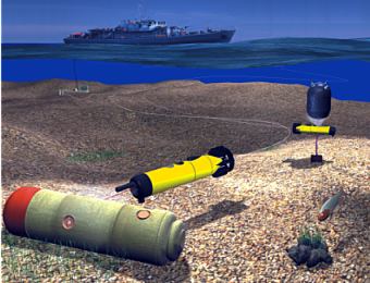
| Self propelled Mine Counter charge
is used to identify and destroy naval mines. Its
target can be located at least 300m from a launch
point. Typical mission profile calls for identification
and destruction of a target detected by other means.
Normally it will be detected by means of mine hunter's
bow sonar. Missions against targets stored in data
bases is also very likely.
SMCC is a disposable, torpedo like, small remotely
operated vehicle. It carries mine disposal equipment
to detected and classified target. While target
is identified by vehicle sonar and TV camera this
equipment is used to initiate mine explosive. Specific
feature of one of SMCC versions is vertically oriented
shaped charge. For the shaped charge or semi armor
piercing (SAP) gun, an aiming procedure is required.
This is achieved using SMCC maneuvering abilities
and laser aiming device. While properly aimed, the
device is triggered by means of coded signal sent
from operators console. Accidental triggering of
a mine fuse also means mission success.
If the disposal device is not triggered by the operator,
during a defined time, the SMCC computer neutralizes
the fuse and is able to flood its pressure hull
with sea water.
SMCC is available in two versions. Version armed
with a mine counter charge, is a disposable, single
mission device. Training and reconnaissance version
of SMCC is identical, with exception for lack of
the charge. It is recovered after a training or
reconnaissance mission has been finished. |
| 2. Navigation
|
| Mine counter
mission consists of a few distinguished periods.
It starts with a short launch phase followed by
transition to target area. Constant tracking of
SMCC position is critical in transition phase. Tracking
is accomplished by means of acoustic transponder/responder.
It is fixed to vehicle body and responds to ultra
short base line navigation system or ships mine
hunting sonar. Relocation phase in friendly environment
lasts a few minutes. While struggling with strong
currents it can take 15 minutes for the SMCC to
reach a target area. To facilitate operator work
in this phase, an automatic control procedure can
be selected. This integrates data from tracking
system, vehicle data and navigation data of the
mission platform (ship). Together with environmental
information (currents) these data allow for calculation
of optimum path and vehicle parameters. During next
mission phase, the target must be found using vehicle
sonar and TV camera.. Auto heading and auto depth/altitude
are usually utilized but manual control is compulsory
in this phase.. This is also true for the following
identification and aiming phases. |
| 3. SMCC system completion
|
| Basic set delivered
is composed of the following elements:
SMCC (armed) in transporting case 10 pcs
SMCC (training) in transporting case 2 pcs
Operators console 1 pc
Launcher in transporting case 1 pc
Launcher winch 1 pc
Launcher lifting cable 1 pc
Recovery net 1 pc
Hydroacoustic navigation system
antenna 1 pc
Maintenance equipment set 1 pc
Spare parts set 1 pc |
|
 |
| 4. Technical specification |
| Operating depth: 200
m
Maximum speed: 3 m/s
Range: 500m
Mission duration time (total maximum) 30 minutes
Mine disposal device:
1. Shaped charge with 2kg of explosive, vertically
or horizontally mounted
2. Qinetiq's SAP projectile gun
3. Other devices up to 8kg mass
External dimensions of SMCC:
-length total : 1,400m (1,600m armed with SAP gun)
-width with stabilizers: 0,360m
-height with stabilizers: 0,360m
Mass: 45,0kg
Buoyancy: +1,0N to 2,0N
Propulsion:
-four, 3 blade screw propellers in horizontal plane,
electrically driven, 50 W power each
-single vertical thruster, electrically driven 3
blade screw propeller in a tunnel, 50 W power
Energy source: Lithium ion accumulator battery
nominal voltage: 24V
nominal capacity:16Ah C1
Controls: Remote, computer aided, using single
optical fibre of 2000m length
Mass of SMCC and optical fibre dispensers
in transporting case: 60,0 kg |
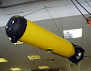
| Basic
components of SMCC |
4.1 Mine disposal
devices
SMCC is prepared to carry two types of mine disposal
devices. They are located in vehicle bow section.
Less expensive is shaped charge. It is metal lined
to increase capability to initiate mine explosive
charge. Depending on target specification, shaped
charge is pointed horizontally or vertically. Vertical
charges are used against moored and partly buried
mines. Qinetiq designed SAP projectile gun is installed
as alternative. It is understood that the gun is
more effective against non sensitive explosives
and mines buried in sediments. Charge type and orientation
is being selected according to local conditions.
4.2 Observation and navigation equipment
To achieve high navigation accuracy, SMCC system
uses comprehensive set of navigation equipment.
Different devices are of prime importance during
mission phases defined below. USBL hydroacoustic
navigation system leads vehicle during transition
to a target area. Diving depth and altitude are
measured simultaneously. While in the area, scanning
sonar and TV camera provide required information.
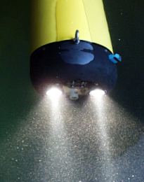
Complete set mounted on the vehicle consists of:
|
1. Two B&W TV cameras
2. Three lamps
3. Scanning sonar
4. Two laser aiming devices
5. Magnetic compass with pitch and roll sensor
6. Echosounder as altitude meter
7. Pressure sensor as depth meter
8. Transponder/responder for hydroacoustic navigation |
|
| |
4.3 Pressure hull
Majority of SMCC vehicle components are installed
inside a single pressure hull. It consists of cylindrical
body closed by bow and stern, covers. The covers provide
all pressure penetrations and support all internally
mounted devices. This way components are divided between
two interconnected units that can be mounted after
completely assembled. Bow section contains battery
and mine counter charge while rear is devoted to control
computer and propulsion motors. The pressure hull
is streamlined externally with plastic covers that
are built around sonar head and optical fibre dispenser.
4.4 Vehicle Controller
Vehicle control system consists of several components
both inside and onboard the ship.
The vehicle part is composed of: SMCC on board computer
Signal multiplexer
Arming and safety module
The on board computer collects sensor data and sends
information to operator's console. The console returns
commands that are used to govern speed of propellers
and other actuators.
4.5 Pitch control
SMCC is basically neutrally trimmed. This condition
is checked before packing. During transit phase
of a mine counter mission, required pitch is achieved
by means horizontal propellers thrust control. To
allow accurate aiming, large pitch angles may be
required. This is accomplished by means of internal
ballast, that changes vehicle centre of gravity.
Accumulator battery, moved by stepping motor, is
used for this purpose. Angles of up to 30 are achieved
steplessly.
5. Operator's console
SMCC is controlled
by trained operator. He uses navigation data, sonar
and television image . To allow operator to concentrate
on a single screen, most important data are overlayed
on TV signal. His work is further supported by navigation
computer that integrates data from the hydroacoustic
navigation system and platform's (ship) navigation
sensors. It can also run several automatic procedures
and use information from a ships mine hunting sonar.
SMCC can be controlled using two types of consoles.
Both are build of the same modules and runs the
same software.
|
| |
|
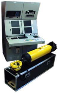
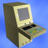
5.1 Permanently installed Operators Console
Operators Console is designed to be permanently
mounted in ships operating room. It is integrated
with ships command and navigation system. Console's
steel enclosure is composed of several modules with
external dimensions that allows transport through
600mm door openings. Modules located above control
panel contains four 12
LCD displays, Trackpoint II command module and TV
signal management equipment. Two screens are used
for TV signals from SMCC and launcher or deck. Two
other screens accept SVGA signals from sonar and
navigation computers.
A single screen console is also available. It uses
large size high resolution LCD to display four scalable
windows. Membrane keyboard can be replaced with
a touch sensitive configurable LCD panel |
Console contains the following computers in separate
enclosures:
1. Control computer
2. Sonar computer
3. Navigation computer
4. Built-in trainer simulator computer
5. Sonar head simulator (optional)
6. Second TV image simulator
|
Single
screen operators console |
| |
| The following
devices are
mounted on a control panel
and used to command the
system:
! Control keyboard
! Sonar control terminal
! Two axis joystick A
! Single axis joystick B
! Arming and firing unit
Selected command function can be switched to the
portable controller to help in deck operations. |
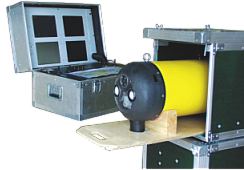
| 5.2
Portable operator's console
Portable operator's console can be mounted on ship
of opportunity, helicopter or ashore. Four 10 LCD
screens are used to reduce size and weight. The
built in trainer computer has been removed for the
same reasons. Functions of other components are
the same or similar.
Basically operator's console case
contains:
1. Control computer 2. Sonar computer
3. Navigation computer 4. Optical communication
components
The permanently mounted console contains
command module of hydroacoustic navi-gation system,
video recorder, remote control unit receiver and
UPS. In a case of portable system, these components
are supplied as separate units. This allows easy
arrangement of required components in confined spaces.
|
| |
| 5.3 Remote controller
Portable remote controller is a part of operator's
console. It is a convenient device, used by deck
personnel to control SMCC while floating at the
surface. Principally it is utilised to lead the
training vehicle into the recovery net. It is also
very helpful during pre-dive and post-dive check
procedures. The remote controller contains a radio
transmitter. It sends signals read by microprocessor
from two joysticks and buttons. Components are enclosed
in a sealed, fibre reinforced plastic box. Receiver
within operator's console transfers control signals
to computer system, using RS232 wire link.
5.4 Vehicle movement control
Two analogue joysticks and a keyboard is used to
control the SMCC in water space. Settings are read
by console control computer, processed and sent
to vehicle computer via RS232, implemented on fibre
optic link. The on board computer controls all the
vehicle functions including propulsion electric
motors and stepping motor driving a ballast weight.
5.4.1 Control in transition phase
During transition at relative speed of 2m/s to 3
m/s, SMCC movements are articulated by means of
changes of speed of propellers. Vertical thruster
and trimming ballast are not in use. To change thrust
vector of propulsion propellers operator uses single
two axis joystick (A) located on right side of the
console. Automatic guiding procedure can replace
operator in this phase of a dive.
5.4.2 Control during approach, identification
and aiming
High demands to maneuvering abilities during these
phases calls for use vertical thrusters and trimming
ballast. Their operation is executed manually by
means of buttons (ballast) and left side mounted
joystick. Vehicle trim can be changed statically,
using movement of ballast weight (battery) or dynamically,
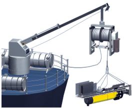
adjusting thrust of propulsion propellers. 5.6 Launch
SMCC is launched using dedicated equipment. It consists
of a SMCC launcher and an electro-mechanical winch.
The winch is used to lower the launcher with suspended
vehicle close to a sea bottom. The launcher uses
electrically operated catchers to firmly hold the
vehicle. Launch procedure can be monitored by operator
by means of launcher mounted TV camera. While free
from the launcher the SMCC swims to a target area
carrying one of the optical fibre dispensers. Other
fibre dispenser is fixed to the launcher. A fins
are mounted at down stream end of the launched body.
The fins direct launcher against a current, to assure
the SMCC is always launched with a current. The
solution was selected to protect optical fibre against
damage, caused by waves and sea currents and platform
(ship) movements. |
|
5.6 Launch
SMCC is launched using dedicated equipment.
It consists of a SMCC launcher and an electro-mechanical
winch. The winch is used to lower the launcher with
suspended vehicle close to a sea bottom. The launcher
uses electrically operated catchers to firmly hold
the vehicle. Launch procedure can be monitored by
operator by means of launcher mounted TV camera.
While free from the launcher the SMCC swims to a
target area carrying one of the optical fibre dispensers.
Other fibre dispenser is fixed to the launcher.
A fins are mounted at down stream end of the launched
body. The fins direct launcher against a current,
to assure the SMCC is always launched with a current.
The solution was selected to protect optical fibre
against damage, caused by waves and sea currents
and platform (ship) movements.
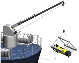
5.7 Recovery
It is assumed that training and reconnaissance version
of SMCC is recovered after a dive. To allow this
operation, without use of a boat, a recovery net
is provided with the system. This is suspended on
a ship's crane and lowered to water surface. The
net frame floats on the surface, while the net itself,
forms a bag. To assure required shape net edges
are ballasted with chain, Deck operator drives the
vehicle into the net using portable control unit.
With the vehicle inside the bag, the net and is
lifted to the ships deck.
|
|
| |
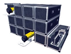
5.8 Cases for transport
and storage
Components of the SMCC system are delivered and
stored in dedicated protective cases. The cases
are strong enough to be stacked in several layers.
Each SMCC, enclosed in air tight polyethylene bag,
rests on the a supporting frame that can pulled
off after its case cover is opened and removed.
It gives easy approach to any vehicle stacked in
warehouse, ship's hold or on open deck.
|
|
|
 |
GDANSK UNIVERSITY of TECHNOLOGY, FACULTY
OF OCEAN ENGINEERING & SHIP TECHNOLOGY,
DEPARTMENT of SHIP DESIGN and SUBSEA ROBOTICS
80-233 Gdańsk, ul.Narutowicza 11/12, Poland
ph. (48 58) 347 19 91, fax: (+48 58) 347 26 99, e-mali: sek8oce@pg.gda.pl
|
|
|