|
|
|
|
|
|
|
|
 |
- R O V - P I L O T - T R A I N E R -
|
| |
1 Introduction
The ROV simulation software has been developed to meet
request of Polish Navy to develop a realistic training
facility for MCM system operators. It was created with
a few limitations assumed:
- The software will be run on IBM compatible, off the
shelf, industrial grade hardware
- Computer simulator will use data from real ROV control
system and simulation results will be presented using
equipment that is utilised in real ROV pilot console.
- Modular software structure is to allow easy implementation
commissioning and modifications.
- Lecture interface will allow easy modifications of environmental
conditions, space
geometry and structures both on the bottom as well as
in water space.
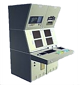
Currently the software is used for simulation of cable
supplied and controlled medium size ROV equipped with
specific manipulation devices. It can be run in dedicated
training console but is also run on computers integrated
into real ROV control console permanently installed in
ships cabin. It allows the ROV pilots to switch the system
to simulator mode and practice simulated missions.
|
 |
 |
|
2 General software characteristics
A kernel of the software is a ROV physics simulator
that calculates vehicle position and orientation changes
as results of control commands and external influences
and limitations. The ROV movement is further limited by
space geometry and umbilical presence.
Specific feature is change of a vehicle geometry due to
action of several components such as pan and tilt units
and manipulators. Space geometry and environmental characteristics
are defined around a vehicle. This includes water surface,
bottom and structures. Optical and acoustical characteristics
are defined for every geometrical element too. Definition
of environmental conditions regards range of features
such as turbidity, current, day time. Local sediment disturbances
and plankton presence are also introduced.
Data regarding current position and orientation in space
together with data regarding space geometry and surface
characteristics are used by specialised software modules
to create images and information presented to a Pilot
using dedicated displays, widows and other adequate means.
For effectiveness and simplicity only one graphical presentation
software module is active in single piece of hardware
(computer). A simulator is built using software/hardware
modules in number required by an application and customer
preferences. In fact, all the modules run the same software
using different device simulation element. Modules are
synchronized by one of them, indicated as master module.
The modules are integrated using local Ethernet network.
The same network is utilized to integrate simulator with
external elements such as vehicle control computers, navigation
computers and other devices required to make virtual reality
close to real as much as possible. 8 modules are currently
run including one dedicated to lecturer or training supervisor.
Principal feature of the software used for simulation
is ability to generate required results in real time.
Simulation step lasts 1/30s that assures good perception
of presented images by human operator.
|
|
3 Device simulation modules
Several device simulation modules were developed to meet
ROV simulator needs.
Principal are TV and sonar space image simulators. These
are supplemented by 2 navigation modules, supervisor and
space editors. |
| |
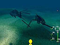
3.1 TV camera imager The module
uses data regarding camera position and orientation. Orientation
depends on vehicle orientation as well as current pan
and tilt axes position. Externally mounted camera view
can be also selected to facilitate training of a vehicle
dynamics and space awareness.
A pilot view presented on display is deteriorated by environmental
conditions defined generally for a mission to be performed
by a trainee. Application of several software/hardware
camera modules can simulate all the vehicle cameras simultaneously.
|
 |
| |
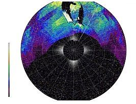
3.2 Sonar imager
Sonar imager is self efficient module that uses data
similar to that used by TV camera imager. To build the
image module uses ray tracing metords developed. Several
acoustic characteristics can be adjusted to achieve simulation
quality according to local requirements.
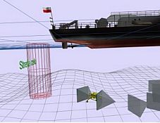
It is wise however to simulate behaviour of specific sonar.
It means use of standard (for the make) sonar controls
and screen appearance. To achieve this requirement sonar
imager generates sonar head data that are fed to other
computer running sonar image presentation software.
In current application Tritech Seaprince head is simulated.
Sonar data are than supplied to computer containing AIF
3 card running SONV3 software. Tritech SCU RAT is used
to control head activity. Standard Seaprince communication
protocol implemented on RS232 is used for this purpose. |
|
 |
The solution allows easy modifications
to follow sonar changes and changes to other sonar systems.
|
 |
| |
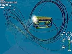
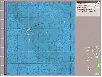
3.3 Navigation
Two types of navigation modules are run in trainer and
can be selected for other applications.
One is typical module, running simulation software and
displaying data projected on bathymetric map with indication
position of selected features (transponders, targets etc).
ROV symbol with an umbilical length and shape are overlayed
on bathymetric map to help pilot to act against currents.
Bathymetric map of the area can be loaded in electronic
form of agreed format.
Other module is navigation data integration computer
that gathers data from ROV control system, hydroacoustic
navigation system, and ship's navigation system. Current
tactical situation in geographic coordinates is displayed
to a ROV pilot botch in graphical as well as in alphanumerical
for. The computer is external to the simulator itself
but uses data generated when simulator is running.
|
 |
| |
4 Lessons and high level modifications
4.1 Lessons To allow a pilot to develop mental and
manual skills several lessons are prepared. One can start
from experimental tank navigation with defined coordination
training. This allows to get familiar with vehicle dynamics
and principles of interactions with manipulated objects.
More task oriented lessons can follow with difficulty
increase. The lessons can be utilised both in training
end skills evaluation (exams). Further lessons can be
created using dedicated script language according to expected
mission tasks and conditions.
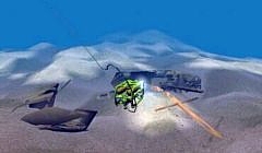
4.2 Space editor
Current space definition is limited to 400m x 400m area.
Using space editor a training supervisor is able to customise
ROV operational space. Basic operation is to build bottom
geometry. This is accomplished by simple self graphical
tools similar to that used in drawing programmes. This
is followed by location of objects and structures. Located
objects can be oriented and partly buried in sediments.
Extensive base of objects (mines, stones, coke cans) has
been built for current application. This can be extended
by introduction of any objects that can be defined by
geometry, optical and acoustical characteristics and dynamic
behaviour if object is suspended or can be moved on the
bottom. |
|
| |
4.3 Mission planer
Using means available in simulation software can be used
to prepare current mission environmental and geometrical
data and experiment with several ways solutions of objectives
Best way to accomplish the mission task can be found this
way prior to planned dive.
4.4 3D navigation tool
Application of the simulator graphical and interfacing
capabilities can be used to present current tactical situation
in 3Ds. It is valuable toll for Pilot operating in difficult
spaces such as rig structures, wrecks, caves etc. Data
for this application are to be collected from real ROV
system and presented overlayed on data (in graphical form)
regarding space geometry. |
 |
|
|
5 Range of
an offer
Several options of software/hardware configurations can
be offered to a customer. Basic feedback information from
customer regards:
- Simulation system purpose (training, examination, planning,
real time 3D navigation)
- Vehicle dynamics, visualisation means and manipulation
devices
- Environment data and space geometry
- Installation data (free standing, built in, delivered
as complete trainer)
- Hardware preferences.
Using these information a range of feasible solutions
will be built and offered ranging from single device simulator
running on office PC to the set of modules operating in
or beside copy of customers ROV console. ROV console built
in systems can also be offered in cooperation with vehicle
manufacturer.
|
|
 |
GDANSK UNIVERSITY of TECHNOLOGY, FACULTY
OF OCEAN ENGINEERING & SHIP TECHNOLOGY,
DEPARTMENT of SHIP DESIGN and SUBSEA ROBOTICS
80-233 Gdańsk, ul.Narutowicza 11/12, Poland
ph. (48 58) 347 19 91, fax: (+48 58) 347 26 99, e-mali: sek8oce@pg.gda.pl
|
|
|